|
What are color codes
In electronics, color codes are a a way of labelling of passive electronic components such as resistors and, less frequently, capacitors and inductances. The color coding standard is defined and maintained by the International Electrotechnical Commission and described in the IEC 60062 publication (the document is better known just as IEC 62). Apart from this formal aspect, the two most important reasons for their popularity are:
- Optimal readability:
-
'Reading' a sequence of colored rings painted around cylindrical resistors is much easier then reading a sequence of serigraphed numerals on objects of the same size - especially when environmental conditions are not optimal (think about a dimly lit interior of a console cabinet containing a hard-to-access printed board).
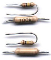
The rings are visible from all possible angles even when the component is mounted on an already deployed board, while numeric labels tend to follow the Murfy's law and often end up facing either the board or a nearby component (they may be hard to read even when the board is physically available for close inspection). This is illustrated by the Figure on the right which shows a pair of resistors, one color-coded and one with a numeric label, viewed from two different angles (top and bottom).
For the same reason, picking a resistor of a particular value from an assorted bunch (such as a serviceman's toolbox) is much easier when they are color coded.
- Low cost:
In automated production, marking small cylinders with colored rings is much easier than printing numbers on them. Talking about objects whose production cost is in the 0.1 cents range, this is very important.
Color coding basics
Step 1: Primarily, the coding associates a color with a numeral from 0 to 9 as indicated in the second and third columns of Table 1. There beeing ten such numerals, it is evident that color coding is strictly decadic.
Step 2: A series of color bands is read replacing mentally each consecutive color with the corresponding numeral, interpreted as a decadic digit. Thus the color-bands sequence brown-black-yellow of the resistor in the above Figure is read as 104.
Step 3: The possible values of electronic components typically cover many decades. Since it would be cumbersome to encode, say 15 MΩ resistor as brown-green-black-black-black-black-black-black. For this reason, the code implements what amounts to a floating-point convention. The last numeral is interpreted as a decadic exponent of a multiplier factor. From the list of multipliers in Table 1 (columns three and four) it is evident that, essentially, one just adds as many zeros as is the value of the last digit.
As an example, consider again the sequence brown-black-yellow of the last paragraph. Since the last digit is 4, the value it denotes is actually 1 0 0000 (i.e., 100 kΩ), but should the sequence be brown-black-black, the multiplier would be just 1 (zero zeros added), ending up with 10 Ω.
The concept of decadic multiplier has led to the introduction of two more color-coded values denoting negative exponents - golden for 1/10 and silver for 1/100. These are particularly useful for coding resistor values. To make an example, the sequence red-violet-silver denotes the value of 0.27.
| |
Table 1. Color codes used on passive electronic components
Color |
|
digit |
|
Multiplier:
10^digit |
|
Resistors:
tolerance |
|
Temp.coef.
ppm/°C |
|
Inductors:
tolerance |
| Silver |
|
(-2) |
|
*0.01 |
|
10% (K) |
|
not used |
|
10% |
| Golden |
|
(-1) |
|
*0.1 |
|
5% (J) |
|
not used |
|
5% |
| Black |
|
0 |
|
*1 |
|
not used |
|
not used |
|
20% |
| Brown |
|
1 |
|
*10 |
|
1% (F) |
|
100 |
|
1% (mil) |
| Red |
|
2 |
|
*100 |
|
2% (G) |
|
50 |
|
2% (mil) |
| Orange |
|
3 |
|
*1 000 |
|
not used |
|
15 |
|
3% (mil) |
| Yellow |
|
4 |
|
*10 000 |
|
not used |
|
25 |
|
4% (mil) |
| Green |
|
5 |
|
*100 000 |
|
0.5% (D) |
|
not used |
|
not used |
| Blue |
|
6 |
|
*1 000 000 |
|
0.25% (C) |
|
10 |
|
not used |
| Violet |
|
7 |
|
*10 M |
|
0.1% (B) |
|
5 |
|
not used |
| Gray |
|
8 |
|
*100 M |
|
0.05% |
|
not used |
|
not used |
| White |
|
9 |
|
*1 G |
|
not used |
|
1 |
|
not used |
| None |
|
|
|
|
|
|
|
|
|
20% |
| |
The rainbow connection

The roots of color coding are simple, romantic and physically meaningfull. The codes for numerals 2 to 7 were in fact inspired by the progression of colors in a rainbow (check it against the photo on the right), starting from the lowest frequencies (longest wavelengths) on the outer rim and proceding towards the highest ones (shortest wavelengths) on the inner side. We all know, of course, that there is a golden pot buried at the base of every rainbow. This, alas, is where electronic color codes deviate sharply from the romance, since a golden band stands for a rather unsatisfactory 5% tolerance on the nominal value ...
The colors for the remaining digits are also easily accounted for. The brown color (corresponding to 1) can be interpreted as black with a trifle bit of red in it and thus logically preceeds the red one. The values corresponding to 0, 8 and 9 (black, gray and white, respectively) were added in order to include the black-to-white range of pseudo-colors and, in addition, to reach the desired number of ten basic values. Naturally enough, they are arranged in a way to make the black and the white colors fall on the opposite sides of the sequence.
This basic color scheme is - or at least should be - the preferred one also in other contexts. For example, targets for archers should follow them, starting with black (0) as the innermost color and following the sequence outward in ten concentric rings.
The extensions for the multiplier factors (golden and silver) were added as an afterthought and thus, I believe, are purely conventional.
Color-coded resistors

Color-codes of resistors are basically restricted to the two categories listed below and consist of a group of bands encoding the resistor's value and a band encoding its tolerance (the maximum allowed deviation from the nominal value). The values are always expressed in Ohms. The bands denoting the value are should be kept close together and start at one edge of the resistor, while the tolerance band is often isolated by a larger gap.
- Four-color codes:
A four-color code consists of a 3-color code for the numeric value (two bands for mantissa and one for exponent), followed by a single color-band code for tolerance class. The tolerance classes covered by the 4-color codes are ±10% (silver), 5% (golden) and 2% (red).
The Figure on the right shows realistic examples of resistors with 4-band codes. The resistors are intentionally of various makes and not quite new. All of them have the tolerance class of 5% (golden), except the last one which has 10% (silver). From top down, their ohmic values in are:
1.2, 10, 15, 33, 47, 68, 820, 2.7K, 2.2K, 33K, 100K, 1M and 3.9M.
The second resistor from the top exemplifies the fact that one must pay attention to the orientation - unlike all the others, this one must be read from right to left (there is no doubt in this case, since a golden band is not a valid starting digit). In addition, the interpretation of the color bands against various background colors of the resistor body is sometimes not trivial and requires a bit of practice and, as an additional guidance, the knowledge of conventional resistor values. Thus, for example, I had some trouble recognizing the color of the second band in the 2.7K resistor as violet. Remembering, however, that the only standard values in the interval between 2 and 3 are 2.2 and 2.7, I have opted correctly for the latter since the band is clearly of a different color that the first one. Likewise, there could be a confusion between the values of 2.2K (tree red bands) and 33K (three orange bands). When in doubt - and when it is possible - don't hesitate to use your faithful tester to check (which is what I did in this case).
- Five-color codes:
-
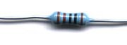
Five-color codes are very similar and consist of a 4-color code for the numeric value (three bands for mantissa and one for exponent), followed by a single color-band code for tolerance class. The tolerance classes covered by 5-color codes are ±1% (brown), 0.5% (green), 0.25% (blue), 0.1% (violet) and the almost purely theoretical 0.05% (gray).
The Figure on the right shows a color-coded 1000 Ω resistor of ±1% tolerance class. Notice that in this case there is a legitimate doubt about orientation. Reading the colors from right to left, one in fact ends up with 1100 Ω which is a fully legitimate value for this tolerance class (in order to resolve the doubt, I had to use my tester again). The producer of this resistor should have distanced the tolerance band a bit more from the numeric value bands.
Temperature coefficient band:
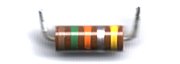
Occasionally, one can encounter resistors with either six color bands or resistors with five bands, the last one of which the last one is anomalous for a tolerance class specification (orange, yellow or white). In such cases, the last band defines the worst-case temperature-dependence coefficient of the component. The codes for temperature coefficients are listed in Table 1. As an example, the picture on the right shows a 15kΩ ±10% resistor with a temperature coefficient not worse than 25 ppm/°C.
Temperature-tolerance color-coding is used very rarely and may differ slightly among producers. Consequently, whenever you see something out of ordinary, be careful, use your tester and, if still in doubt, check with the supplier.
Color-coded inductors
Though color coding of electronic component follows always the same general rules, minor differences between different component types do occur. In the case of small inductors, only two color-coded digits are used to encode the mantissa and one to encode the multiplier. The resulting values are expressed in µH (micro-Henrys). Since miniature inductors greater than 10 mH are impossible to produce, multipliers greater than 10000 (yellow band) never occur.
A small improvement in readability is achieved by allowing the golden multiplier band (*0.1) to be used also as a decimal point. This means, for example, that sequences black-red-golden and black-golden-red encode the same value of 1.2.
Standard tolerances for inductor values are ±20% (missing or black color band), 10% (silver) and 5% (golden). As indicated in Table 1, tolerances of 1, 2, 3 and 4 % are foreseen only for military-grade components.
Military inductors are optionally countersigned by a starting silver band (usually wider that the others), especially when the tolerance band does not already imply a military grade.
Color-coded capacitors

For some reason, color coding of capacitors is much less widespread than color coding of resistors and inductors (it used to be quite frequent but, at present, capacitor producers seems to be moving away from it). The fact may have something to do with the typical shapes of small capacitors, but the argument, if valid at all, is not very straightforward. In any case, exceptions do exist.
Whenever a capacitor is color-coded, its value is expressed in pF (pico-Farads). Thus the values of the two capacitors on the right are 15 nF (15*1000 pF) and 1 nF (10*100 pF). I am not sure, though, about the meaning of the final two color bands. Should any Reader illuminate me, I would be most grateful.
|