|
Introduction
Any NMR instrument which uses the same induction coil to both excite the nuclei and to detect the subsequent free induction decay (FID) is subject to artifacts due to imperfect separation between the high-power excitation branch (gated transmitter) and the low-power signal-detection branch (preamplifier and gated receiver) which meet at the coil terminals.
The basic transmitter-receiver separation consists in the fact that the two devices never operate simultaneously - the sample is first excited by a very brief but powerful RF pulse and only afterwards starts the acquisition of the much longer lasting but very weak FID signal. Even so, however, one must face several problems. First of all, one must protect the preamplifier from being damaged during the high-voltage pulse. Second, no matter how good such a protection might be, it is never perfect and the preamp needs some time to recover from overload during the pulse. Third, the probe circuitry is a tuned circuit and reacts to the pulse by a ringing tail which has nothing to do with the NMR signal. The result is that for some time after the pulse, the detected signal is heavily distorted and/or contains pulse-ringing artifacts. The duration of the interval during which the receiver is 'blinded' is called dead time td and can be expressed as
(1) td = max(tp, tt, tr),
where tp is the probe-ringing time, tt the transmitter ringing time, and tr the receiver recovery time.
In most cases the transmitter ringing is much shorter than probe ringing and may be neglected.
For the purposes of this discussion we will anyway consider it as lumped together with probe ringing.
The dead-time gives rise to a number of characteristic, pesky artifacts in the acquired data. In particular, it causes rolling baselines in high-resolution NMR spectroscopy, distortions of wide lines in low-resolution NMR, and image artifacts in MRI. It is therefore always desirable to reduce it as much as possible.
The receiver recovery time tr would be zero if the preamplifier protection during the pulse were good enough to prevent any overload. In practice, however, this is not easy to achieve. Consider that the RF pulse voltage may be as large as several hundreds of volts, while the FID signal can be as small as a few microvolts, amounting to a ratio of over 160 dB. Even if we consider just the preamplifier saturation level (typically of the order of a few tens of millivolts), it still implies that the separation needs to be of the order of about 80 dB.
It follows that a satisfactory separation is always a problem. A large number of possible solutions, both passive and active (gated), has been proposed in the literature and the search for still better ways is still going on.
A classical solution
NMR and MRI instruments operating at low and moderate Larmor frequencies (up to 200 MHz) often implement a simple, passive transmitter-receiver separation based of wave-propagation properties of coaxial RF cables and on the switching capabilities of fast diodes. A well-known 'λ/4' arrangement due to I.J.Lowe and C.E.Tarr [2,15] is shown in Figure 1. Though not perfect, it is still quite competitive with more sophisticated designs - especially since the latter often cure one aspect of the problem while introducing new types of artifacts.
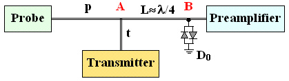
Figure 1. Classical transmitter-receiver isolation using a λ/4 cable and crossed diodes
The probe is usually a tuned device operating at a central frequency f, while the preamp may be broadband. The probe and the preamplifier are both matched to the same effective input impedance Z0 (usually 50 Ω) coincident with the characteristic impedance of all the coaxial cables.
During the pulse, the transmitter feeds power into the probe. Since the probe is matched, there are no reflected waves and the cable lengths p,t are irrelevant. It also means that the voltage at point A goes through full peak-to-peak swing, identical to that at the transmitter output (just shifted in phase). When the length L of the coaxial cable between points A and B is one quarter of the wavelength of the propagating radio frequency, point B can be shorted to ground without damaging the transmitter. This is because such a short represents an unmatched termination which causes the formation of a standing wave with a null node in B. For reasons which will be discussed in the next paragraph, however, point B may not be shorted to the ground in a 'hard' way. Rather, one uses a pair of crossed diodes which approximate a short for strong RF signals but leaves the connection open for signals smaller than the diode threshold voltage.
During signal detection the transmitter output is in high impedance and the NMR signal propagates from the probe into the preamplifier. As mentioned above, since the signal is much smaller than the diode turn-on voltage, it is as though the diodes were absent. Moreover, since the preamplifier is matched, there are no reflected waves and the cable lengths p,L are irrelevant.
The arrangement works quite well but nevertheless suffers from several practical drawbacks. First of all, the crossed diodes at B do not represent a perfect short during the pulse. Second, the required matching of impedances is never perfect so there are always some standing waves even on the sections where there should be none. Third, it is impractical to have λ/4 cables ready for each and every frequency that will be ever used. Usually one has a finite set of such cables and uses each of them to cover an interval with a certain center frequency fc and a width which is something like +/- 10% of fc. Consequently, total deviations from the ideal are sometimes as large as 15%.
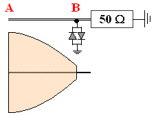
Figure 2. RF envelope along the λ/4 cable between A and B
As a result (see Figure 2), there is always some residual power drain from the transmitter into the crossed diodes. During the pulse, the diodes get heavily overloaded and partially depleted of charge carriers. Consequently, the actual peak-to-peak voltage in B, though much smaller than that in A, is often still too high (10 V or more) to avoid preamplifier overload and saturation.
An improvement
One can improve the situation by placing two or more crossed diodes pairs between point B and the ground. This makes point B a more perfect short for large signals and also helps the diodes to sustain the leaked power.
But what about something a bit more sophisticated?
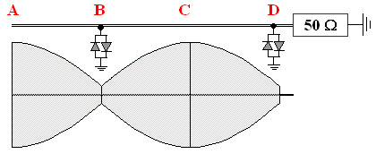
Figure 3. RF envelope along the cable between A and the preamplifier after adding a λ/2 section
What if we add a section BD of cable of length λ/2 terminated at D by another pair of crossed diodes (Figure 3). When there is a residual RF at point B, this will make the section BD oscillate as shown in Figure 3, with the peak-to-peak maximum of the standing wave occurring at the mid-point C. The maximum amplitude in C is practically the same as in point A, but the associated standing-wave power is much smaller since most of the incident power has been reflected back at point B (the voltage in C could be dramatically reduced by even a relatively small ohmic load in C). The fact is, however, that the extra λ/2 cable does not solve our problem - it merely translates it from point B to point D.
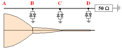
Figure 4. Further improvement: connecting C to the ground by a pair of crossed diodes
To achieve a real improvement, one must quench the standing wave in the section BD. The easiest way to do so is to short-circuit point C to the ground by a pair of crossed diodes as shown in Figure 4. In this way one produces a chain of identical sections, each composed of a λ/4 cable and terminated by a pair of crossed diodes. When the transmitter is enabled, all the nodes where the diodes are located reflect the incoming RF power back to where it came from. Increasing the number of such sections, there is a rapid convergence of the residual pulse RF amplitude towards a constant level with a peak-to-peak voltage given by the threshold (0.65 V) of the diodes.
Notice that this falls in place with design criteria for using diodes as RF switches. It is well known that the ON/OFF power ratio reliably achievable with a single crossed-diode pair does not exceed 40 dB. Since we need at least twice as much, it is clear that multiple switching 'stages' should be used.
One should not exaggerate the number of the λ/4 sections, however, since the noise generated by all the crossed diodes placed along the detection path will eventually affect the overall sensitivity (S/N ratio). Fortunately, as far as noise is concerned, the diodes are all connected in parallel which helps to keep in check the combined noise they produce. Even so, however, there is a limit to the number of devices (of any type) one may connect to the signal-input path without having to pay for it.
Practical considerations
Limiting the number of sections to three is probably the best choice. The diodes should be all very fast ones (1-5 ns nominal recovery time). The final circuit is shown in Figure 5 below.
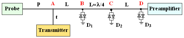
Figure 5. A realization using three λ/4 sections, each terminated by a pair of crossed diodes
The incident power is largest at point B and drops rapidly along the chain B-C-D. This means that the crossed diodes placed in B should be particularly good and capable of sustaining the largest overloads - a reason why they may be of a different type than those in C and D and why it may pay off to make them double or triple. Vice versa, the diodes in D are already protected by those which precede them and need to be just fast but non necessarily robust. Consequently, it may be a good idea to further enhances the preamp protection by using in D germanium diodes instead of silicon ones (0.2 V threshold instead of 0.65 V).
The exact diode types to be chosen depend upon the actual powers to be handled and upon the expected usage of the transmitter. When passing from 100W pulses to 1 kW, or when using long-lasting irradiations like in T1ρ measurements, it may be best to resort to high power microwave switching diodes; otherwise, low cost devices such as the classical 1N4148 may suffice.
The final diode pair is often mounted directly inside the preamplifier (the short gap between the last section and the preamp in the above Figures is purely symbolic and intended to make the drawings a bit simpler).
To limit any pick-up of environmental electromagnetic noise, the coaxial cables should be all double-screened. Their characteristic impedance must be Z0 (the same as the effective impedance of the tuned probe). The λ/4 length L can be computed for any operating frequency f from the speed of signal propagation along the cable - a parameter supplied by the cable producer which, however, is almost invariably about 0.65% of the speed of light. When that is the case, we have approximately
(2) L = 48/f [meters].
The output of the transmitter power amplifier is usually connected to the circuit through an in-series pair of crossed diodes (not shown) which isolate it when the transmitter is OFF and block its output noise from contaminating the signal. Since such diode switches are non-linear, however, linear (A-class) power amplifiers may frown upon them and use instead sophisticated noise-blanking circuits operated via an external gate.
Applicability and Comments
The multiple λ/4 chain all but eliminates the preamplifier recovery time. Whether it reduces the NMR front-end dead time, however, depends upon the probe and transmitter ringing times. According to equation (1), when the latter dominate, the multiple λ/4 chain will not help. We can therefore expect this technique to be useful mostly with low-Q probes in which the ringing is short (such probes are typically used to measure samples with very broad lines).
On high-Q probes the ringing is sometimes reduced by means of actively gated switches which affect the probe's tuning and/or Q-factor. In such cases, the preamplifier recovery time may again become important and the multiple λ/4 chain might lead to a still shorfter dead time.
Apart from the dead-time problem, there is one more reason why good transmitter-receiver isolation may be of importance. When overloaded, some preamplifiers undergo a variation in the first-stage operating point (no doubt because of a partial rectification of the input RF). The result is a transient variation in gain which can last much longer than the nominal recovery time and which depends upon the degree of the initial overload. From the above exposition it is clear that multiple λ/4 chains can eliminate this problem. This instrumental artifact can adversely affect data collected in experiments involving long trains of refocussing pulses (such as CPMG sequences) or T1ρ type irradiation periods.
According to equation (2), at frequencies above 200 MHz the λ/4 cables become too short to manage (less than 10 cm at 500 MHz). From the above discussion it follows that one can use a cable whose length is any odd multiple of λ/4, which is one way to alleviate the problem. Another way, often adopted also at low frequencies, is to use lumped-circuits of various kinds, the simplest of which simply simulate a λ/4 cable. In the latter case, cascading several such circuits, each terminated with a pair of crossed diodes, will still have the desired effect.
There is an important safety consideration which applies to all transmitter-receiver separation schemes based on λ/4 coaxial cables and diodes, or on their lumped-circuit emulations. Make sure that you never apply to the system high-power RF with a grossly incorrect frequency. If you do so, the first crossed diodes will become not a standing wave node but a real short on the transmitter output with the result that you soon either burn the transmitter or burn the diodes!
|